Tiếng Việt
Consulting, Industrial Automation, News
Comprehensive Article on Harmonics: What are Harmonics? Structure, Effects & Solutions
Harmonics are one of the biggest issues concerning power quality, causing severe losses and risks to modern industrial and civil electrical systems. Understanding what harmonics are, their causes, and effective harmonic filtering solutions is key to protecting equipment and optimizing operating costs.
What are Harmonics?
The Concept of Harmonics in Electrical Systems
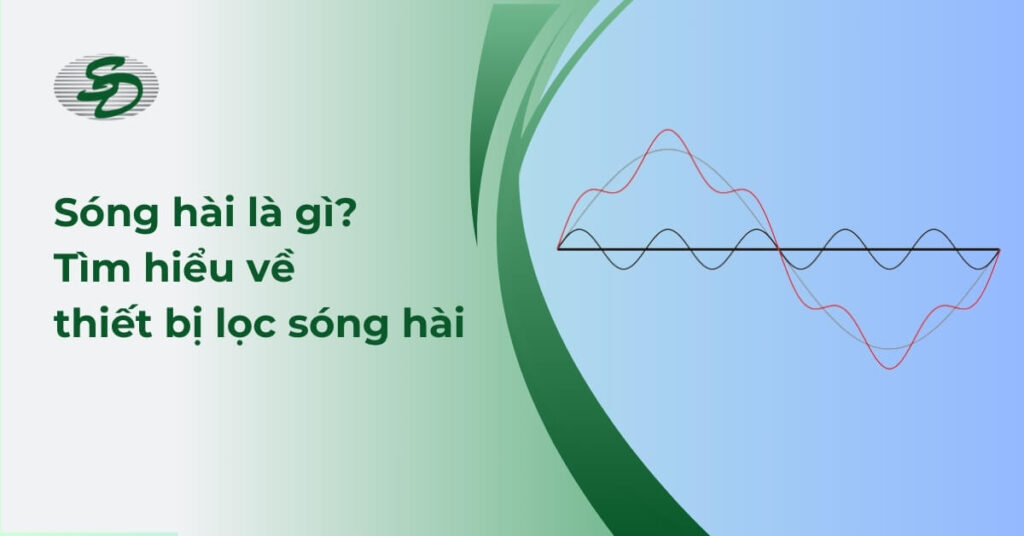
Harmonics are sinusoidal voltage or current components whose frequencies are integral multiples of the system’s fundamental frequency (typically 50 Hz or 60 Hz).
In an ideal electrical system, the current and voltage are perfectly sinusoidal at the fundamental frequency (f_b). However, the presence of non-linear loads distorts this waveform, creating a mixed, non-purely sinusoidal waveform.
According to Fourier Analysis theory, any periodic non-sinusoidal electrical waveform can be analyzed into the sum of:
- Fundamental Component: The sinusoidal wave at the basic frequency (50 Hz).
- Harmonic Components: A series of higher-frequency sinusoidal waves, which are the harmonics.
The harmonic frequency (f_h) is calculated as the product of the harmonic order (h) and the fundamental frequency (f_b).
- h is the harmonic order (a positive integer: 2, 3, 4, 5, …).
- f_b is the fundamental frequency (e.g., 50 Hz).
- Example: For f_b = 50 Hz, the 5th harmonic will have a frequency of 5 x 50 Hz = 250 Hz.
Harmonics do not carry useful power for the load but are mainly converted into thermal energy (due to increased copper loss), causing energy loss and reducing equipment lifespan.
What is Total Harmonic Distortion (THD)?
Total Harmonic Distortion (THD) is a crucial index used to quantify the overall degree of distortion of the voltage or current waveform compared to an ideal sinusoidal waveform. This is a quantitative measure of the “cleanliness” of the electrical waveform.
The THD formula is based on the ratio between the total root mean square (RMS) value of all higher harmonic components (from the 2nd order upwards) and the RMS value of the fundamental component. The higher the THD, the more severely the waveform is distorted.
- Low THD (typically < 5%): The waveform is close to the ideal sine wave, and the system operates efficiently.
- High THD (typically > 10%): The waveform is severely distorted, risking faults, overheating, and system collapse.
What is Harmonic Order (h)?
Harmonic Order (h) is the ratio between the harmonic frequency and the fundamental frequency, determining the nature and impact of that harmonic.
- 1st Harmonic: This is the fundamental component (50 Hz).
- Higher Harmonics: Orders 2, 3, 4, … are components with frequencies 2, 3, 4, … times the fundamental frequency.
Causes of Harmonics in Electrical Systems
The core cause of harmonics is the presence of Non-linear loads. Non-linear loads are devices where the relationship between consumed current and applied voltage is not linear (it does not follow the simple Ohm’s law R=V/I). They often use rectifiers to convert AC to DC, causing the current drawn by the load to be chopped (only drawn at the peaks of the sine voltage) and to be non-sinusoidal even when the supply voltage is a perfect sine wave.
Harmonics vs. Electrical Noise
| Feature | Harmonics | Electrical Noise (Noise/EMI) |
|---|---|---|
| Nature | Sinusoidal wave, frequency is an integral multiple of the fundamental frequency (n times 50 Hz). The waveform is predictable. | Random signal, electrical impulse, very high frequency (typically greater than or equal to 2 kHz), not integral multiples. |
| Origin | Non-linear loads (VFDs, UPS, SMPS, Arc Furnaces). | Sudden switching phenomena, electrical discharge, lightning, mechanical switching devices. |
| Impact | Increased thermal loss (I^2 R), neutral conductor overload, reduced efficiency of transformers and motors. | Communication errors (PLC, Data), data loss, interference with electronic control signals. |
| Solution | Specialized harmonic filters (AHF, PHF, Reactors). | EMI/RFI filtering, shielded cables, good grounding/shielding. |
Classification of Harmonics
Harmonic classification helps identify the source and select the appropriate mitigation solution.
Low-Order Harmonics (3, 5, 7) – Greatest Impact
These are the most common and typically have the largest magnitude, causing the most severe effects.
- 3rd Harmonic (Triplens): Particularly dangerous in 3-phase, 4-wire systems (with a neutral wire). Because they are zero-sequence components, they do not cancel out but add up in the neutral wire, potentially increasing the neutral current up to 3 times the phase current. This leads to overheating, burning of the neutral wire, and transformer failures if the transformer is Delta-Wye connected.
- 5th and 7th Harmonics: Most frequently encountered due to 6-pulse loads (like 6-pulse VFDs, standard rectifiers). They create a magnetic field that rotates counter to the fundamental magnetic field in motors and generators, reducing useful torque, increasing vibration, and causing severe overheating.
High-Order Harmonics
These usually have smaller magnitudes, but if present, they can cause faults in sensitive electronic equipment, increase high-frequency losses in magnetic cores, or interfere with communication control systems.
Odd and Even Harmonics
- Odd Harmonics: Orders 3, 5, 7, 9, … Most symmetrically operating non-linear loads (VFDs, UPS) only generate odd harmonics. This is the most common type.
- Even Harmonics: Orders 2, 4, 6, … Usually generated by unbalanced load operation or differences in the characteristics between the positive and negative half-cycles of the device (e.g., welding machines, arc furnaces, or DC Offset errors). The presence of even harmonics is often a sign of malfunction or severe load imbalance.
Harmonic Generation Sources by Order
The generated harmonic order is closely related to the structure of the non-linear load, especially the number of rectifier pulses (q-pulse).
- 6-Pulse Load (Common): Generates orders h = (k times 6) plus or minus 1. Results in orders 5, 7, 11, 13, 17, 19, …
- 12-Pulse Load (Less Common): Generates orders h = (k times 12) plus or minus 1. Mainly generates orders 11, 13, 23, 25, … (significantly reducing orders 5 and 7).
Effects of Harmonics on Electrical Systems
Harmonics negatively affect almost all components in the electrical system, leading to increased operating costs, reduced efficiency, and safety risks.
On Industrial Electrical Equipment
- Winding Overheating, Equipment Failure: Harmonic currents significantly increase the overall Root Mean Square (RMS) current. The increased RMS current leads to increased thermal losses according to the copper loss formula I^2 R. Local overheating occurs due to increased Eddy Current losses, which rise with the square of the frequency.
- Reduced Equipment Lifespan: Prolonged high temperatures degrade the quality of insulating materials, accelerating the aging process and severely reducing the lifespan of motors, transformers, and cables.
- Reduced Motor Efficiency: The 5th and 7th harmonics create a counter-rotating magnetic field, reducing the motor’s useful torque, forcing the motor to draw more current to maintain speed, resulting in lower efficiency.
On VFDs – UPS – Data Centers
- Overcurrent/Overvoltage Trip Errors: Harmonics cause false voltage and current peaks, leading protective devices (relays, sensors) in VFDs/UPS to trip or unnecessarily disconnect the circuit.
- System Collapse, Controller Reset: Harmonic voltage distorts the sine wave of the grid voltage, affecting the sampling capability and stable operation of sensitive control units (PLC, VFD) and potentially causing the entire production system to collapse (reset or trip).
On the Grid & Transformers
- Increased Energy Loss: Harmonic currents increase losses on the power grid and within the transformer windings.
- Abnormal Heating and Derating: Transformers overheat abnormally due to increased Foucault current and Eddy current losses, which rise with the square of the frequency. Transformers with high harmonic content must be derated according to the ANSI/IEEE C57.110 standard.
Effective Harmonic Mitigation Solutions
Harmonic mitigation solutions focus on eliminating harmonic currents at the source or preventing their propagation into the system, ensuring THD remains within acceptable limits (typically below 5% I_THD).
Harmonic Filtering using Reactors
Reactors are a basic and cost-effective solution, often installed with non-linear loads like VFDs to improve current quality:
- AC/DC Harmonic Filtering Reactor: Installed at the input (AC) or DC link of the VFD. The reactor helps flatten the current waveform, reducing I_THD from 40% down to approximately 30%-35%. This is a modest reduction, often insufficient to meet stringent standards.
- Tuning Reactor (Detuning Reactor): This is a mandatory solution when installing capacitor banks (for power factor correction). The reactor is installed in series with the capacitor to create an LC resonant circuit with a natural frequency lower than the dangerous harmonic orders (typically 4.2 times the fundamental frequency, equivalent to 210 Hz), shifting the resonance point away from the 5th (250 Hz) and 7th orders, preventing dangerous resonance that can cause capacitor bank failure.
Passive Harmonic Filter (PHF)
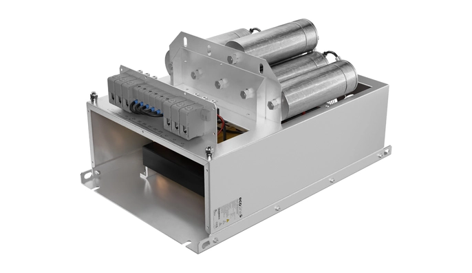
- Structure and Principle: A PHF is a combination of inductors (L), capacitors (C), and resistors (R) designed to form an LC resonant circuit with extremely low impedance at one (or several) specific harmonic frequencies (e.g., filtering only the 5th and 7th orders). The harmonic current will be “sucked” into this filter circuit instead of flowing back into the grid.
- Application & Limitations: Suitable for large, fixed loads. Limitations: Large size, easily overloaded or damaged when grid resonance frequency changes, only filters pre-determined harmonic orders, and can cause excessive reactive power compensation leading to overvoltage.
Active Harmonic Filter (AHF) – High-Technology Solution
- Structure: Uses modern power electronics technology (IGBTs) and a high-speed Digital Signal Processor (DSP) controller.
- Operating Principle (Counter-Phased Current Injection): The AHF operates in parallel with the non-linear load. The controller continuously measures the harmonic current generated by the load. The AHF then generates a compensating harmonic current with the exact same magnitude and a 180-degree opposite phase to the load’s harmonic current (counter-phased current injection method). When this compensating current is injected into the grid and combines with the load’s harmonic current, they cancel each other out, making the total current drawn from the grid nearly a perfect sine wave.
- Superior Advantages over PHF:
- Multi-Purpose Filtering: Can filter multiple harmonic orders simultaneously (typically up to the 50th order).
- Flexibility: Automatically adjusts the compensating current to adapt to rapid load changes (e.g., robots, welding machines).
- Active Functionality: Can also compensate for reactive power (reducing the need for additional capacitor banks).
- Significantly smaller size compared to PHF.
When to Choose AHF vs. PHF? (Comparison Table)
| Criteria | Passive Harmonic Filter (PHF) | Active Harmonic Filter (AHF) |
|---|---|---|
| Filtering Efficiency | Filters only pre-determined harmonic orders, efficiency decreases with THD changes. | Multi-order filtering (up to 50th), high efficiency (> 95%), stable. |
| Load Adaptability | Poor (Efficiency decreases as load changes). | Excellent (Automatically adapts to load changes within milliseconds). |
| Resonance Risk | Risk of causing resonance with the power grid if not precisely designed. | Does not cause resonance, can even mitigate system resonance. |
| Cost | Often lower than AHF (for the same power rating). | Often higher but more flexible and effective. |
| Suitability | Large, fixed loads, requirements for low-order harmonic filtering, low cost is a priority. | Sensitive loads, continuously changing loads (Data Centers, Robots, Multi-level VFDs), reactive power compensation required. |
Implementation Process for Harmonic Mitigation in Factories – Data Centers
The standard process to ensure that the harmonic mitigation solution achieves optimal effectiveness and complies with standards.
1. Detailed THD Survey & Measurement
Use a specialized Power Quality Analyzer to measure and record V_THD, I_THD, and the detailed harmonic spectrum at the Point of Common Coupling (PCC) and main busbars. Data should be continuously collected for a sufficiently long period (a minimum of 7 days according to standards) to capture the working cycle and load changes of the facility.
2. Non-linear Load Analysis
Identify the total power, quantity, and characteristics of each type of non-linear load (VFDs, UPS, SMPS). This analysis helps determine the total harmonic current the system is injecting and the magnitude of the main harmonic orders (primarily 5th, 7th, 11th, 13th, and 3rd Triplens).
3. Calculation & Selection of Optimal Solution
Based on measurement and load analysis results, calculate the required filtering capacity (kVAr) and select the filtering technology (AHF, PHF, or Reactor combination) to ensure that V_THD and I_THD after filtering are below the acceptable thresholds of the standards (e.g., IEEE 519 typically specifies I_THD at the PCC below 5-8% depending on the short-circuit capacity).
4. Installation – Commissioning – Continuous Monitoring
Install the harmonic filter panel at the optimal location (near the harmonic source or at the main busbar), then run commissioning tests. After installation, power quality measurements must be taken again to verify the filtering effectiveness. Implement a continuous monitoring system to ensure filtering performance does not degrade over time or with load changes.
Servo Dynamics Engineering: Official Authorized Distributor of Schaffner in Vietnam
As the official authorized distributor of Schaffner in Vietnam, Servo Dynamics Engineering is committed to providing high-quality harmonic filtering solutions (AHF, PHF) and reactors, helping customers completely resolve power quality issues, ensure stable operation, and save costs. Contact us for professional consultation, survey, and harmonic mitigation implementation.